Green's theorem with multiple boundary components
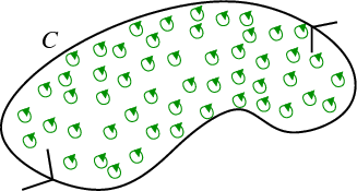
In our initial presentation of Green's theorem, we stated that the total circulation of a vector field $\dlvf$ around a closed curve $\dlc$ in the plane is equal to the double integral of the “microscopic circulation” over the region $\dlr$ inside $\dlc$, \begin{align*} \lint{\partial \dlr}{\dlvf} = \iint_\dlr \left( \pdiff{\dlvfc_2}{x} - \pdiff{\dlvfc_1}{y}\right)dA. \end{align*} (Here we write $\dlc=\partial \dlr$ to show that $\dlc$ was the boundary of $\dlr$.) We illustrated the idea behind Green's theorem with this sketch showing the “microscopic circulation” in $\dlr$ as little green oriented circles. We need $\dlc$ to be oriented in a counterclockwise fashion. Although we didn't stress it in the initial reading, Green's theorem, of course, requires that $\dlvf$ be defined everywhere inside $\dlr$.
As usual, we like to keep our initial presentations as simple as possible, so we don't include all possible complications. It turns out that Green's theorems applies to more general regions that just those bounded by just one simple closed curve. We can also use Green's theorem for regions $\dlr$ with holes in them, such as with the region between the red and the blue curves sketched below. In this case, the requirement is that $\dlvf$ is defined everywhere in $\dlr$, though it doesn't need to be defined inside the holes.
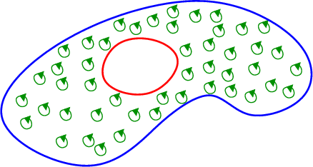
In the above picture, $\dlr$ has a single hole in it. Hence, the boundary $\partial \dlr$ has two components (the red and the blue curves). Green's theorem still says that the integral of the “microscopic circulation” in $\dlr$ is equal to the line integral of $\dlvf$ around the boundary. But now the line integral of $\dlvf$ around the boundary is really two integrals: the integral around the blue curve plus the integral around the red curve. If we call the blue curve $\dlc_1$ and the red curve $\dlc_2$, then we can write Green's theorem as \begin{align*} \lint{\dlc_1}{\dlvf} + \lint{\dlc_2}{\dlvf} = \iint_\dlr \left( \pdiff{\dlvfc_2}{x} - \pdiff{\dlvfc_1}{y}\right)dA. \end{align*}
The only remaining question is how to orient $\dlc_1$ and $\dlc_2$. Just as in the top picture without a hole, we require that the outer boundary $\dlc_1$ be oriented in a counterclockwise fashion. Notice that with this choice, the orientation of $\dlc_1$ matches the orientation of the green circles. For example, the top parts of the green circles are oriented to the left. Since the tops of the green circles touch the top of $\dlc_1$, the top part of $\dlc_1$ must be oriented to the left in order to match. Both the green circles and $\dlc_1$ must have a counterclockwise orientation.
Now, look closely at the orientation of the green circles near $\dlc_2$ (the inner red curve). Again, the orientation of $\dlc_2$ must match the direction of the green circles. But, this time, the tops of the green circles touch the bottom of $\dlc_2$. Since the tops of the green circles are oriented to the left, the bottom of $\dlc_2$ must also be oriented to the left. This means $\dlc_2$ must actually be oriented in a clockwise fashion.
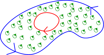
We end up with a simple formula for determining the orienations of all the parts of the boundary $\dlc = \partial \dlr$. The outer boundary must have a counterclockwise orientation. Any inner boundaries surrounding holes in $\dlr$ must have a clockwise orientation. As before, we say that such a $\partial \dlr$ is a positively oriented boundary of $\dlr$.
We can also describe the requirement for a positively oriented boundary using the right hand rule (which is how we'll discuss orientation of boundaries in the closely related Stokes' Theorem). The “microscopic circulation” denoted by the little green circles is oriented to coincide with the orientation of the curled fingers of your right hand if you point your right thumb out of the computer screen. If you place your right hand with thumb up in the region $\dlr$ and move it so that your fingers are next to any of the boundary components, the orientation of the boundary must coincide with the direction of your fingers. For the right hand rule to work, it is crucial that your hand be inside the region $\dlr$. In this case, your hand will be inside $\dlc_1$, showing that $\dlc_1$ must be oriented counterclockwise. Since your hand must be outside of $\dlc_2$ to be inside $\dlr$, the right hand rule shows $\dlc_2$ must be oriented clockwise.
Thread navigation
Multivariable calculus
- Previous: Using Green's theorem to find area
- Next: The idea behind Stokes' theorem
Math 2374
Notation systems
Similar pages
- The idea behind Green's theorem
- When Green's theorem applies
- Calculating the formula for circulation per unit area
- A path-dependent vector field with zero curl
- The idea of the curl of a vector field
- Subtleties about curl
- The components of the curl
- Line integrals as circulation
- Other ways of writing Green's theorem
- Using Green's theorem to find area
- More similar pages